Skip to product information
1 of 3
Vendor: TENSE

Digital overcurrent relay with voltage protection and 3×3-digit LED display TRM-30F

Barcode: TRM-30F
Regular price
€53,04
Regular price
Sale price
€53,04
Low stock: 5 left
  • Description
  • Payment methods
  • Warranty

Monitoring overcurrent relay TRM-30F with display, 3-phase up to 25A

It is designed to protect equipment sensitive to operating current and voltage values from faults that may occur due to:

  • current overload (adjustable current value 0.5 ... 30 A)
  • current asymmetry (50%, fixed value)
  • voltage asymmetry (30%, fixed value)
  • overvoltage and undervoltage (Umin: 265 V, Umax: 440 V, fixed value)

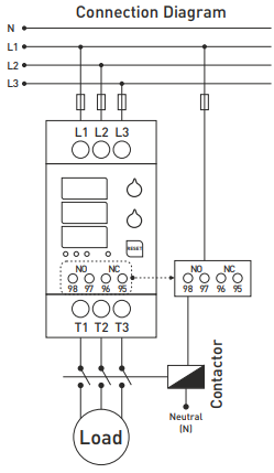
With the TRM-30F digital overcurrent relay with display, you can view the current in each phase and protect the motor or device against overcurrent, overvoltage, undervoltage, phase failure, and phase reversal. These digital overload relays are designed to prevent damage to the motor/load caused by high currents, while the current in each phase can be monitored on the display. They can also monitor the cumulative voltage values between phases.

Thanks to the two output relays (1x NO, 1x NC), it is also possible to control or switch off the load when an overcurrent setpoint is reached, or to activate a signaling contact to the control system. The TRM-xx digital relays have built-in current transformers and a 3x3 digit display for current indication.


Application and operating principle

  1. Connect the device according to the wiring diagram. Incorrect connections can damage the device.
  2. Set the device's overcurrent with the ">A" controller according to the operating current of the load you are going to monitor.
  3. When the current is connected, the set overcurrent value appears on the top display within the first second and the fault delay time on the middle display.
  4. The actual values of the phase currents are displayed after one second and the indicator LED lights up.
  5. If the "V/A/RESET" button is pressed, the values of the combined voltage between the phases are displayed.

Drivers

  • "A>" - setting of the allowed overload; the value is displayed on the top display.
  • "sec." - setting of the delay time for the overcurrent fault; the value is displayed on the middle display.

Contact status

  • NO 95-96, NC 97-98:
    • Device without power or in fault: NO open, NC closed.
    • Device powered and without fault: NO open, NC open.

LED indication

  • LED "V" - lights up in case of overvoltage/undervoltage or asymmetric voltage fault.
  • LED "A" - lights up in case of high current or current asymmetry fault.
  • LED "XI" - lights up in case of phase sequence error.
  • LED "NOR" - lights up when the device is powered and the system is fault-free.

Function of the "V/A/RESET" button

  • Reset: Pressing for 3 seconds clears the fault, LED "A" turns off, NO contact closes, NC contact opens.
  • V/A: Short press switches the display between current and voltage values.

Protection and operating principle

1. Overcurrent protection (0.5-30 A):

  • Entering fault condition: when the set overcurrent is exceeded, the set time is waited. Phase display flashes, LED "A" lights, NO open, NC closed, LED NOR off.
  • Fault condition exit: current below setpoint, hold reset pressed for 3 seconds.

2. Protection against current asymmetry:

  • Entry: current difference between phases >50%, wait 3 seconds, display flashes, LED "A" lights.
  • Exit: difference <50%, press reset for 3 seconds.

3. Overvoltage protection (U>440 V):

  • Entry: voltage >440 V, wait 3 seconds, display flashes, LED "V" lights.
  • Exit: voltage <435 V for 3 seconds.

4. Undervoltage protection (U<265 V):

  • Entry: voltage <265 V, wait 3 seconds, display flashes, LED "V" lights.
  • Exit: voltage >270 V for 3 seconds.

5. Protection against voltage asymmetry:

  • Entry: voltage difference >30%, wait 3 seconds, display flashes, LED "V" lights.
  • Exit: difference <30% for 3 seconds.

6. Phase sequence protection:

  • Incorrect phase connection causes LED "XI" to light up.

Calculation of current asymmetry

The instrument calculates the asymmetry according to the formula:


Example: ((25 - 15) / 25) × 100 = 40% current asymmetry.


Technical specification

  • Supply voltage: measured voltage 3f 3x400 VAC
  • Operating voltage (Un): 3x380 VAC 50/60 Hz, own power <10 VA
  • Adjustable overload (Overload): 0.5-30 A
  • Fault waiting time (t): 0-20 s
  • Display: 3x3 digits, 9 mm high, 7 indication LEDs
  • Overvoltage: 440 V (L-L)
  • Undervoltage: 265 V (L-L)
  • Voltage asymmetry: 30%
  • Current asymmetry: 50%
  • Waiting time for asymmetry fault: 3 s
  • 2x output relays (1x NO, 1x NC): 3 A / 250 V AC (resistive load)
  • Connection type: screw terminals
  • Cable cross-section: 2.5 mm² (relay contacts) / 6 mm² (input and output loads for measurement)
  • Weight: max. 380 g
  • Mounting: on DIN rail
  • Operating temperature: -20°C ... +55°C
  • Altitude for use: <2000 m

Online payment by card – after completing the order, you will be redirected to the payment page. The payment confirmation will be sent to your e‑mail.

Cash on delivery (COD) – you pay the amount directly to the driver upon delivery.

By bank transfer – at the latest on the next working day, you will receive a pro-forma invoice by e‑mail with the account number to which you can pay.

On invoice – this payment option is available for partners who have concluded a framework agreement with our company.

If you want to use one of the last two payment methods, please contact our business manager. He will explain to you how to receive an invoice with or without VAT.

The electrical equipment we supply meets high quality standards, has a 24-month warranty, and fully complies with all EU requirements.

In case of a complaint, no return costs will be charged.

You might also like this

Recently viewed products